
Regarding the coupling, what's not coming apart -- the shaft coupling from the transmission coupling or the shaft coupling from the shaft?
On our boat we sprayed everything with WD40 everyday for a week before any of the nut/bolts would move. You can also use something like PB Blaster. But 1 or 2 squirts aint gonna do the job. So it'll probably take you several days of squirting penetrant on everything.
After we were finally able to remove all of the nuts/bolts/set screws and separate the shaft coupling from the transmission coupling, here's how we got the shaft coupling separated from the shaft.
Go to Home Depot, Lowes or the nearest hardware store and get some long bolts, about 6" in length. Make sure you have nuts that'll fit the bolts and that the bolts will fit through the bolt-holes in the couplings. You'll also need something to use as a spacer. If you have a 1" shaft, the spacer should be narrower than an inch. So a 3/4" OD pipe fitting (like a nipple), that's 3 or 4 inches long will do nicely. Don't use anything wider than that since it has to be able to fit inside the coupling without interfering with the key. You can also use something like a long wrench socket. A handfull of spare nutsand washers that fit or can slide over the long bolts will come in handy too.
- 1. Loosen the nut on the stuffing box.
2. Push the shaft back far enough for you to get the pipe or long wrench socket between it and the transmission coupling. Make sure you line it up so that it butts up against the shaft only (no overlap on the coupling) but closer to the edge opposite the keyway.
3. Push the shaft, with the pipe back up against the transmission coupling.
4. Using the long bolts and their nuts, bolt the two couplings back together making sure that the pipe between them doesn't move. Your contraption will look like this:
<center><img src="http://www.shaftseal.com/pictures/psssh ... upling.gif">
A. Transmission
B. Spacer
C. Bolts
D. Shaft Coupling
E. Transmission Coupling
F. Key
G. Shaft </center>
5. Squirt all around the coupling with WD40, PB Blaster (or whatever penetrant you have) one more time and let it soak in for 10 minutes or so.
6. Tighten each nut slowy, one at a time, only about 1 or 2 turns (NOT MORE THAN THAT) each. You need to do it this way so that you don't bend/brake the bolts or warp or damage the couplings. As you tighten down on the nuts, the couplings will slowly move closer together but the shaft won't be able to move due to the pipe.
7. As the couplings get closer together, you may have to add spacers (spare nuts and/or washers) to the bolts since they'll start to interfere with the transmissioin. So just unbolt everything, add the spacers to the bolts, put the pipe back in place and bolt everything back together. Then continue tightening the bolts as mentioned in step 6.
8. If the pipe or wrench socket isn't long enough, you may need to add some spacers behind or in front of it as well. So you'll need to take everything apart and slide another socket or some nuts and/or washers taped together in there. Bolt everything back together and start tightening the nuts again as mentioned in step 6.
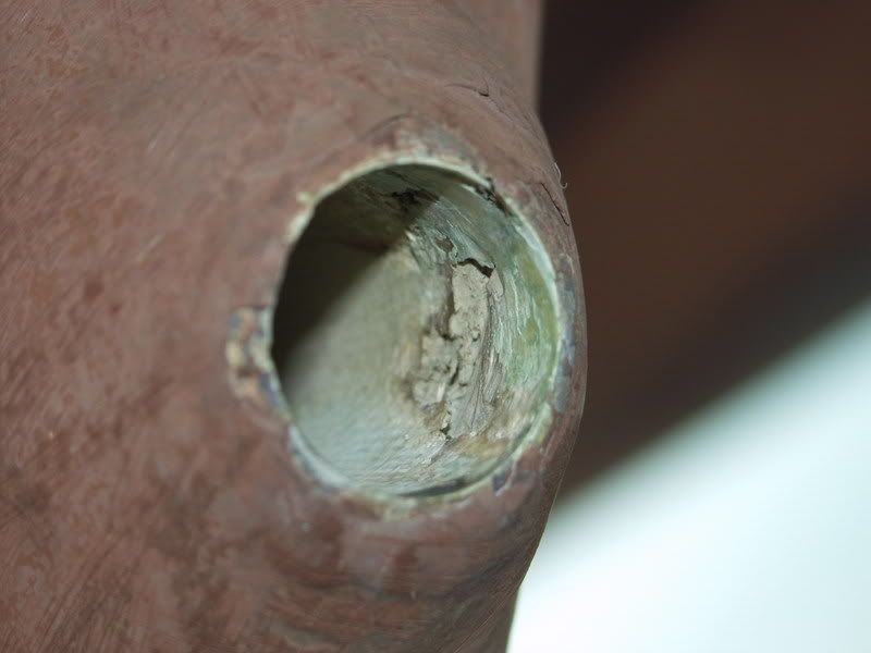
Anyway, here are some photos of our project. Unlike the CD28, which has a bronze stern tube, the CD32 has a fiberglass stern tube. Where the tube exits the boat in the aperture, the tube was originally faired with epoxy completely covering the set screws for the cutless bearing. So I had to grind the epoxy away to get at the old screws. There were 4 holes in the tube for set screws but I think that only 2 had been installed. Only 1 was left, the 2nd screw appeared to have been pulverized. The inside of the stern tube was also damaged where that screw used to be.
<a href="http://i30.photobucket.com/albums/c349/ ... .jpg"><img width="540" src="http://i30.photobucket.com/albums/c349/ ... 083781.jpg">
Note the wide "hump" around the opening of the stern tube. That's all epoxy and had to be ground away. Note also the damage inside the tube. The repair to the inside of the tube is another story.</a>
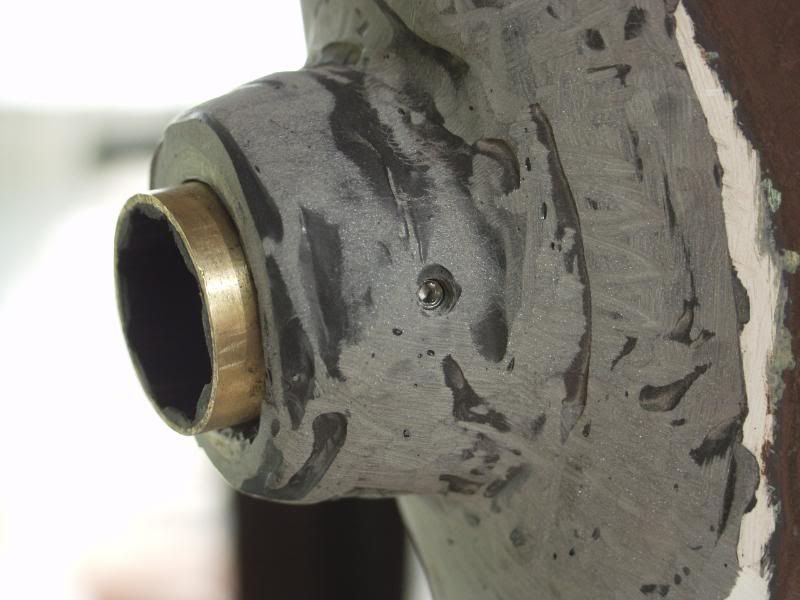
<a href="http://i30.photobucket.com/albums/c349/ ... .jpg"><img width="540" src="http://i30.photobucket.com/albums/c349/ ... 233854.jpg">
The repaired tube with the new cutless bearing in place. The outside of the tube has been built up with epoxy to accommodate longer/larger set screws. We also drilled and tapped for 3 instead of just 2 set screws. You can see one of them in this photo.</a>
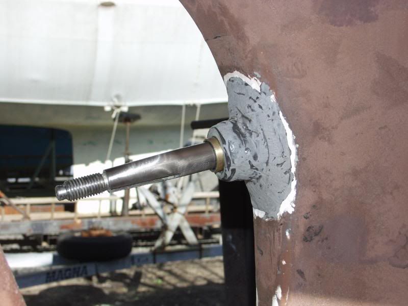
<a href="http://i30.photobucket.com/albums/c349/ ... .jpg"><img width="540" src="http://i30.photobucket.com/albums/c349/ ... 233862.jpg">
The reconditioned shaft in place. Afterwards, I applied two more thick coats of epoxy to build up a new "hump".</a>
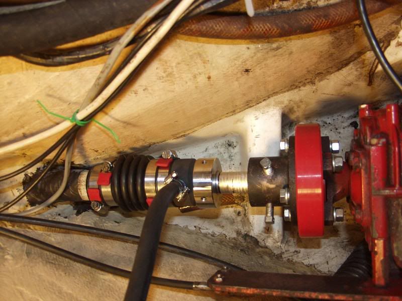
<a href="http://i30.photobucket.com/albums/c349/ ... .jpg"><img width="540" src="http://i30.photobucket.com/albums/c349/ ... 253865.jpg">
The new PYI PSS shaft seal and new DriveSaver installed. Note the tight fit.</a>
Hope this helps,
Cathy
CD32 Realization, #3
Rahway, NJ
Raritan Bay


