A-4 inboard project completed

Don't forget to snap some photos while you work on that boat project, then share them here.

Moderator: Jim Walsh

Post Reply
Hymodyne
Posts: 59
Joined: Jun 8th, '05, 08:51
Location: CD22, Funky Dory,Salisbury, Maryland

A-4 inboard project completed

Post by Hymodyne »

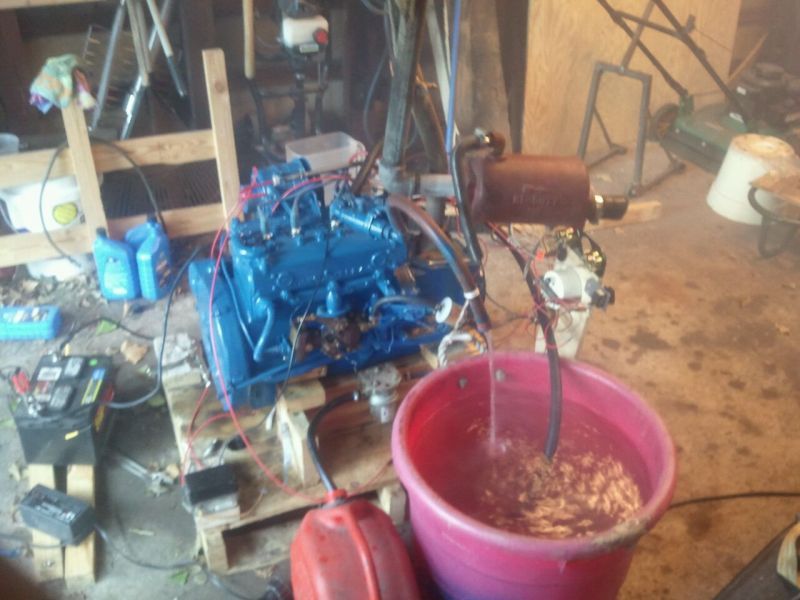
I have always disliked the presence of the outboard kicker on our Dory, so last winter I found an early model Atomic 4 inboard. here it is with the gauges, exhaust and water to test the engine. It was a freshwater engine from lake Michigan :D
Image

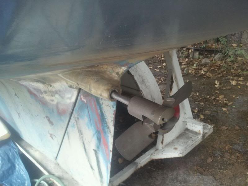
For the final drive I installed an offset 3/4" propeller shaft and folding propeller:
Image
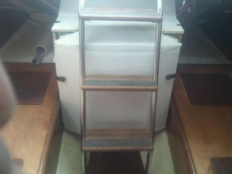
I used insulated pieces of epoxy-covered 1/2" plywood for the side, top and front of the engine compartment:
Image

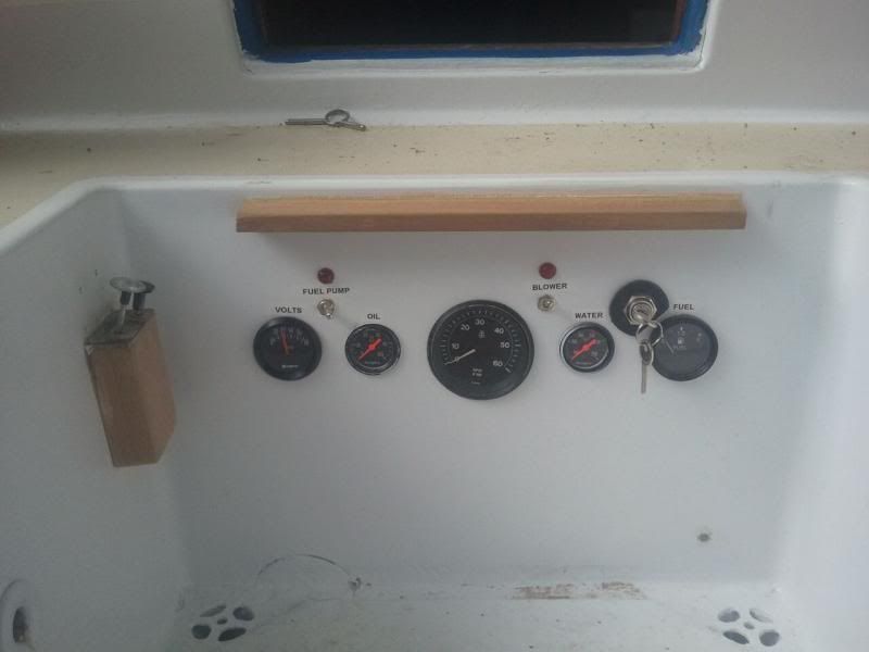
throttle and choke are on the left.
Image

She's been winterized, so this spring, we'll paint and prep to splash on the Nanticoke from Cedar Hill Marina.

James
User avatar
Russell
Posts: 2473
Joined: Feb 5th, '05, 11:14
Location: s/v Lady PaulineCape Dory 36 #117

Re: A-4 inboard project completed

Post by Russell »

Wow, ambitious project! Atomic 4s are great engines, I had one in a previous boat. In a CD22 you certainly will have plenty of reserve power!
Russell
s/v (yet to be named) Tayana 42CC
s/v Lady Pauline Cape Dory 36 #117 (for sale)
pete faga
Posts: 492
Joined: Feb 26th, '05, 20:58
Location: CD25 Grace #66 Scituate Harbor Mass.

Re: A-4 inboard project completed

Post by pete faga »

Good luck with your launch this spring. I would guess this is a first inboard repowering on a 22.
Please post more pictures on this conversion when you get a chance.
How many trips to the chriopractor during installation?
Pete
Hymodyne
Posts: 59
Joined: Jun 8th, '05, 08:51
Location: CD22, Funky Dory,Salisbury, Maryland

Re: A-4 inboard project completed

Post by Hymodyne »

I went ahead and repainted the cockpit and tried out the Rustoleum marine paint and non skid now available at Lowes:
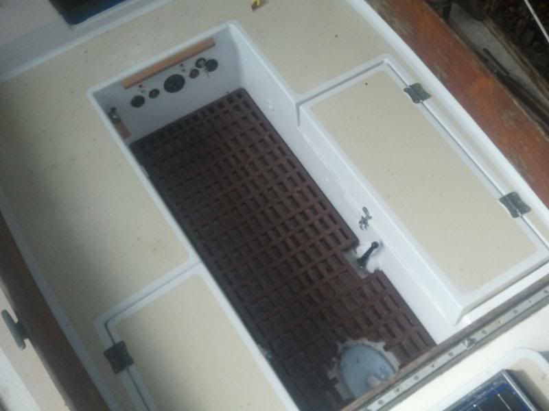
Image

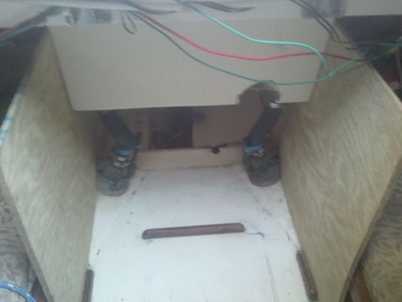
The battery space provided just enough space for the install and compartment:
Image

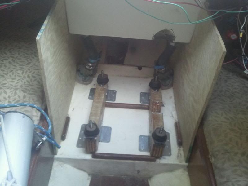
I laminated pieces of 1/2 " plywood together with West Marine epoxy then covered the rails with heavy woven fiberglass cloth and epoxy resin. The engine mounts are from a PWC. Additional pieces of hardwood were placed underneath the fiberglass deck of the battery location to secure the L brackets and wood screws that were holding the rails in place. Lots of put the engine in place, take it back out and measure, adjust to get the rails cut the a proper angle to give the propshaft the correct path out to the keel.
Image

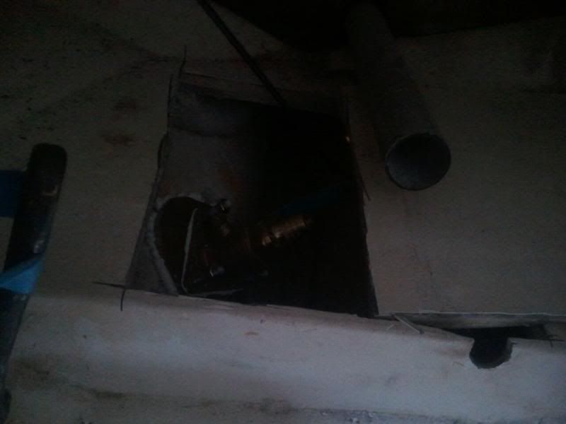
Backing plate and valve for raw water intake
Image

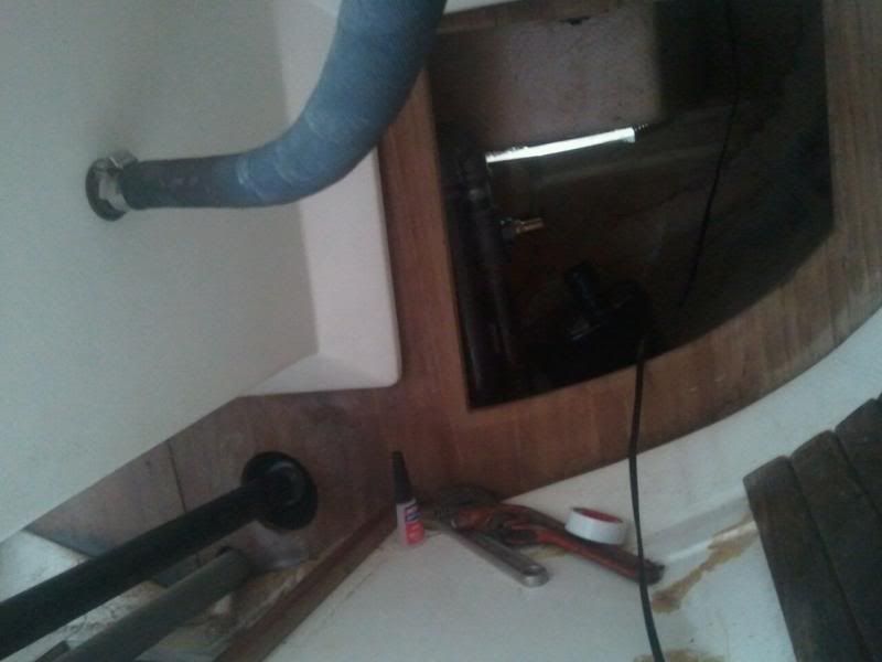
here is the hot section of the exhaust and the propshaft outer tube. The water lift muffler pictured is mounted on the opposite side beneath the seat. after the riser section pictured, the black iron pipe runs across and beneath the cockpit floor, connects to the water lift muffler, which finishes with a section of wet exhaust hose that exits the transon through flap covered through hull.
Image

James
User avatar
Zeida
Posts: 600
Joined: May 27th, '05, 07:10
Location: 1982 CD33 "Bandolera II" Hull #73Key Biscayne-Miami, Florida
Contact:

Re: A-4 inboard project completed

Post by Zeida »

W O W !!!! :!: :!: :!: CONGRATULATIONS!
Zeida
CDSOA Member
User avatar
Gary H
Posts: 399
Joined: Oct 15th, '06, 20:19
Location: 1984 CD 22D "Light Fandango"

Re: A-4 inboard project completed

Post by Gary H »

After seeing this, I will never take the engine in my 22D for granted. Amazing job.
CDSOA Member 1389
Hymodyne
Posts: 59
Joined: Jun 8th, '05, 08:51
Location: CD22, Funky Dory,Salisbury, Maryland

Re: A-4 inboard project completed

Post by Hymodyne »

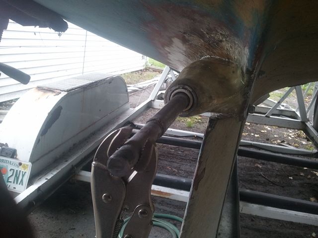
A few more pictures of the project. Mock-up propeller shaft (3/4" steel tube with 5/8" steel rod inside) and mock cutless, a piece of pvc, allowed me to position and finalize the propeller shaft and housing construction long before I got the 3/4" cutless for the keyed stainless shaft. A special drive washer was created at my local machine shop so the shaft would work with the folding propeller. The shaft housing is 6 or so different applications of fiberglass cloth and mat and epoxy and polyvinyl resin. over two sheathed strand fiberglass tubes, with an I.D of 7/8" and a final O.D of 2 1/4"
Image

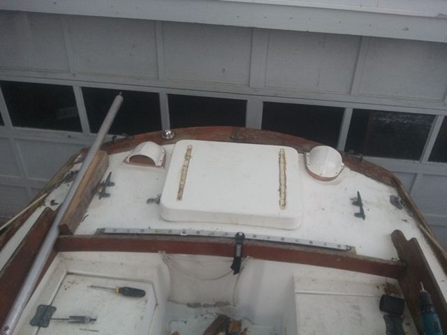
Intake and exhaust vents are seated on 3/4" teak bases. The blower is directly below at the bottom of the rear storage space. 3" hoses are routed to leave space for the 11 gallon tank and fuel hoses.
Image

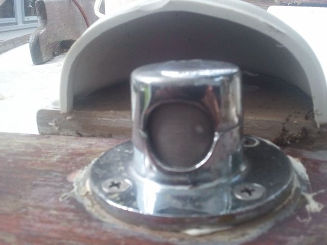
Modified for use as a fuel tank vent; stainless mesh on top and a brass barbed nipple for the hose coming from the tank.

Image

James
Post Reply