Hi all,
I've pretty much exhausted my electrical expertise--took about 2-3 hours, so, I'm looking outward for a bilge pump wiring guru who can help. I'm trying to wire an Johnson Ultima 600 (internal switch) to a Johnson Three way Switch. The directions and labeling have been less than helpful. I've attached pictures of the units with the wires layed out. I get the ground and power that go to the battery, but the brown wires are giving me fits. Any help would be greatly appreciated.
Rusty,
CD 28 "Windigo"
http://s1242.photobucket.com/user/rusty12/library/
Bilge Pump Wiring
Moderator: Jim Walsh
-
Adamhagan
- Posts: 154
- Joined: Jul 6th, '11, 09:48
- Location: 1979 CD30k Eleventh Hour--New York City, NY
Re: Bilge Pump Wiring
I could not make it out in the photo, but the switch should have three positions: 1: auto 2: off 3: manual. Ground is obvious and the brown wire will go to the auto and the brown-white line will go to then manual.
I have a rule system 800 with internal float wired this way and keep my rule 2000 wired with a traditional float switch.
Good luck,
Adam
I have a rule system 800 with internal float wired this way and keep my rule 2000 wired with a traditional float switch.
Good luck,
Adam
Re: Bilge Pump Wiring
Thanks for your response. I think it'd be easier to wire if I did have an external float switch.
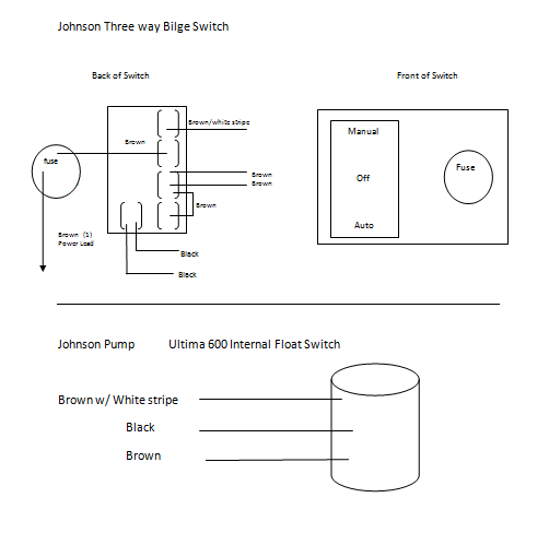
In the photo of the back of the switch, the upper wire (brown w/white tracer) comes from the Manual switch position, and the two brown wires both come from the back of the Auto switch position. The brown and white and the two browns are the ones that are misleading. I know that they should connect to the browns on the pump, but which continues to mystify.
the black ground and the brown coming out of the fuse are obvious.
Rusty
Re: Bilge Pump Wiring
Have A Nice Day
Re: Bilge Pump Wiring
Thank you Sharkbait,
I saw that one but couldn't reconcile it with the instructions that came with the switch. I put a call in to Johnson Pump SPX in Illinois, so maybe that will help. In the meantime, I've made a schematic of the separate parts below. Maybe someone can make sense of it and connect the dots.
Thanks again
Rusty
http://i1242.photobucket.com/albums/gg5 ... 1402357054
Re: Bilge Pump Wiring
Don't like your image site I keep getting spammed about with a "clean your hard drive" link.
There is no problem with your switch other than to many wires. Personally I would yank them all off and start over.
Looking at the back of the switch: On the top set of spade lugs there should be a brown/white wire. Going down to the next set of spade lugs there should be a wire designated 12V+. And, just below that there should be a brown wire on a sett of spade lugs. Note where those wires are and yank all that off and start over. It appears the switch is set up for more than one pump.
Note where the brown/white wire is on the switch and run a wire from the brown/white wire on your pump to that spade lug location on the switch. Should be the top one
Note where one of the brown wires is on the switch and run a wire from the brown wire on your pump to that spade lug location on the switch. Should be the third set of spade lugs.
Note where the wire designated as 12V+ is located. It should the spade lug be between the brown/white wire and the brown wire. Connect fused 12V+ from your 12V buss bar to that spade lug.
Connect a wire from the black wire on your pump to your comm 12V- buss bar.
Have A Nice Day
-
Terry

- Posts: 119
- Joined: Jul 14th, '08, 14:31
- Location: CD-25 Cassandra #567
Lake Lanier, North Georgia
www.jonahzsong.com
Re: Bilge Pump Wiring
This is the first year I've seen any liquid at all in my bilge. It came from a cockpit leak that I didn't seal well. When I pumped out the water, a lot came back in from the hose draining back into the bilge. I'm wondering if there should be a one-way valve in the hose to prevent this from happening. On the other hand, then it would just remain in the hose.
What's the standard practice? Your thoughts on this are appreciated.
Regards, Terry
What's the standard practice? Your thoughts on this are appreciated.
Regards, Terry
Re: Bilge Pump Wiring
Numerous lines of thought on that issue. Check valves in the line will form a restriction could catch debris and preclude any discharge. I prefer to go with the dual pump concept. A small pump in the bottom of the bilge will have a small discharge line and less back flow; this will handle normal drips. Then a larger pump mounted slightly higher with a large hose to handle any emergencies.
Have A Nice Day
Re: Bilge Pump Wiring
Sharkbait,
You fixed it. (And I helped.) It was that extra brown wire on the third position from the top--didn't need it. Everything works fine. I owe you a cold one.
Thanks again,
Rusty
"Windigo"
You fixed it. (And I helped.) It was that extra brown wire on the third position from the top--didn't need it. Everything works fine. I owe you a cold one.
Thanks again,
Rusty
"Windigo"
-
Terry
- Posts: 119
- Joined: Jul 14th, '08, 14:31
- Location: CD-25 Cassandra #567
Lake Lanier, North Georgia
www.jonahzsong.com
Re: Bilge Pump Wiring
Thanks SharkBait. That sounds like a good plan.sharkbait wrote:Numerous lines of thought on that issue. Check valves in the line will form a restriction could catch debris and preclude any discharge. I prefer to go with the dual pump concept. A small pump in the bottom of the bilge will have a small discharge line and less back flow; this will handle normal drips. Then a larger pump mounted slightly higher with a large hose to handle any emergencies.
All the best, Terry