I've been researching the forum for the last day or two in preparation for installing a holding tank in my CD28.
The boat has never had a tank installed but the boat actually came with a nice, clean, never been used tank that "just" needs to be installed. How hard could that possibly be :^)
It is a small (6 gallon) tank with two 1 1/2" top holes and a single 3/4" vent . Based on what I've read I would like to have two vents but I'm going to go with what I have for now.
I got a pretty good handle on what I'm going to do to make this happen but I have a couple of questions.
It may be obvious to others but:
The waste inlet and outlet are both 1 1/2" female threaded for the hose adapters. I don't have a problem with visualizing how the input into the tank will work but I am confused on the pump-out setup.
What is the configuration on the pickup tube for the pump-out? The hose adapter threads into the top of the tank but I have yet to see an actual installation showing a pick up tube going from the top of the tank to the bottom, but I know it must be there. The only thing I can think of is that I will need to glue a length of PVC pipe to the hose adapter that will reach to the bottom of the tank. Is it really that simple?
The other question may be even sillier, some of the hose adapters are barbed and others are smooth. My guess is that the barbed ones are for hose and the smooth ones are for PVC pipe. The guy at WM didn't know the difference.
Wastewater Holding Tank Questions
Moderator: Jim Walsh
-
Steve Laume

- Posts: 4131
- Joined: Feb 13th, '05, 20:40
- Location: Raven1984 Cape Dory 30C Hull #309Noank, CT
- Contact:
-
Steve Laume
- Posts: 4131
- Joined: Feb 13th, '05, 20:40
- Location: Raven1984 Cape Dory 30C Hull #309Noank, CT
- Contact:
Once you start to work with sanitation hose your fears of the hose slipping off of the smooth fittings will be put to rest.johnc wrote:I can see how the smooth fittings would make it easier to get the hose on but wouldn't also make it easier to come off?
If both are for hose what are the pros/cons for each type?
The advantage of the smooth fittings is that you can get the hoses on. I have had to resort to filing down the barbs a bit to make that happen with when barbs were involved. Yes, heat, soap and more than a few choice words are required with the barbed fittings but they are still very difficult to bet on. The smooth fittings are not a sloppy fit but are at least doable in the tight places you may find yourself working.
Cape Dory also made hose replacement interesting, on Raven, by the use of wire ties in areas where they later built non removable cabinetry. I had to enlarge the hole under my stove enough to cut the ties under there.
Sanitary hose replacement was one of the most difficult jobs I have done on the boat, Steve.
Hoses
I've been drawing different configurations, playing what if, to see if I can install a simple system that can easily be expanded.
After laying out several configurations all including pump-out, with and without an overboard option it occurred to me that I really didn't need separate input and output lines from the holding tank, since the system will either be "in use" or being pumped out.
A single hose to the holding tank greatly simplifies things because running hoses seems to be the single biggest pain in this process.
The only complication I can think about is that the input into the tank will have to pass through the pump-out pickup but if that is 1 1/2 inch PVC pipe I don't see a problem. Are there any issues with introducing the waste into the tank from the bottom of the pickup pipe that I am missing? I know that the physics of it say that the pressure on the pump will increase as the tank fills up but the tank is only 16 inches high so how much can that possibly be that the toilet pump can not overcome the additional pressure?
The other advantage of this is that I can use the original input opening as a second vent (the tank only has one vent). Plus if I am going to run two vents one to each side of the boat, I can put an adapter on the 1 1/2 inch opening in the tank down to 1 inch (as recommended by Peggy Hall) for the long run from the tank position, port, to the starboard side.
-
sfreihofer
- Posts: 223
- Joined: Dec 6th, '07, 22:05
- Location: 1981 Cape Dory 25 #794, S/V PEARL
- Contact:
You know, John, what you are contemplating is an interesting idea, and not one I had considered. I like your thinking.
I think it will take a Y valve to select tank inflow vs. outflow. If you want both overboard discharge and deck pumpout, that will require another Y valve. If that is your plan, it may be simpler to just use both 1 1/2 inch ports... two hoses and one valve instead of one hose and two valves... because the valves require three hose connections each, and take up space. If you use both fittings, the fill fitting would not require a pickup tube, of course.
I don't see why it wouldn't work with one hose. The only possible drawback I can imagine is if solid waste gets impacted in the pickup tube. The closer the pickup is to the bottom of the tank, the more likely that possiblity, I would think.
I assume your tank's 1 1/2" ports are threaded. A problem I had was that the pickup tube has to fit inside the threaded fitting, in order to get it into the tank. It took me a while to find pipe that would work.
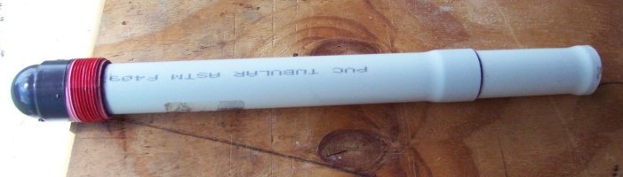
What I used is PVC drain tube for a sink, which I found at Home Depot, in the bathroom section. They come in two lengths. It is a thin wall, which worried me, until I realized that the maximum pressure on the tube would be less than 15 psi vacuum. I also realized that since the tubes have a flared end, you can join short ones together, which doubles the thickness and the joints serve as stiffeners. If I had it to do over, I would use three of the shorter pieces to add more stiffening. The photo below shows one long tube and one short tube joined.
Here is a photo. This is a Schedule 80 elbow, which is stronger than Schedule 40. You can't see the hose barb end, since it is hanging down off the edge of the table, but you can clearly see the threaded portion and the pickup tube cemented inside the fitting. I called it a 'Draw Tube', but your 'Pickup' is a better description.
 [/img]
As for your vent, I wouldn't worry. One 3/4" vent has more cross-sectional area than two 1/2" vents (which I have). Do the math. Your 3/4" vent should be adequate.
It may help you to look at what I've done. All head discharge goes directly to the tank. There is a Y valve to select deck pumpout or overboard discharge.
http://www.reefroof.com/restinterior.htm
There is also a photo here:
http://www.reefroof.com/interiordone.htm
I have made some changes to my installation (by adding an activated charcoal filter to the vent) which I have not updated on the website yet, but for your purposes, these photos may help you.
Stan Freihofer
1981 CD25 #794
S/V Pearl
Ft. Lauderdale
I think it will take a Y valve to select tank inflow vs. outflow. If you want both overboard discharge and deck pumpout, that will require another Y valve. If that is your plan, it may be simpler to just use both 1 1/2 inch ports... two hoses and one valve instead of one hose and two valves... because the valves require three hose connections each, and take up space. If you use both fittings, the fill fitting would not require a pickup tube, of course.
I don't see why it wouldn't work with one hose. The only possible drawback I can imagine is if solid waste gets impacted in the pickup tube. The closer the pickup is to the bottom of the tank, the more likely that possiblity, I would think.
I assume your tank's 1 1/2" ports are threaded. A problem I had was that the pickup tube has to fit inside the threaded fitting, in order to get it into the tank. It took me a while to find pipe that would work.
What I used is PVC drain tube for a sink, which I found at Home Depot, in the bathroom section. They come in two lengths. It is a thin wall, which worried me, until I realized that the maximum pressure on the tube would be less than 15 psi vacuum. I also realized that since the tubes have a flared end, you can join short ones together, which doubles the thickness and the joints serve as stiffeners. If I had it to do over, I would use three of the shorter pieces to add more stiffening. The photo below shows one long tube and one short tube joined.
Here is a photo. This is a Schedule 80 elbow, which is stronger than Schedule 40. You can't see the hose barb end, since it is hanging down off the edge of the table, but you can clearly see the threaded portion and the pickup tube cemented inside the fitting. I called it a 'Draw Tube', but your 'Pickup' is a better description.
[/img]As for your vent, I wouldn't worry. One 3/4" vent has more cross-sectional area than two 1/2" vents (which I have). Do the math. Your 3/4" vent should be adequate.
It may help you to look at what I've done. All head discharge goes directly to the tank. There is a Y valve to select deck pumpout or overboard discharge.
http://www.reefroof.com/restinterior.htm
There is also a photo here:
http://www.reefroof.com/interiordone.htm
I have made some changes to my installation (by adding an activated charcoal filter to the vent) which I have not updated on the website yet, but for your purposes, these photos may help you.
Stan Freihofer
1981 CD25 #794
S/V Pearl
Ft. Lauderdale
Instant Bubble-head. Just add water.
Stan,
Thank you so much for your input.
I was particularly happy to see your pickup tube. I was having some problems visualizing how a completed tube would look. The basic construction of your "draw tube" and my "pickup tube" are very similar. I hadn't thought about the need to make it stiffer but based on your observation I think I will make mine out of three short pieces.
Where your tube differs from mine is on the extreme end of the tube. I envisioned having either a 45 or 90 degree bend to expose the pickup without confining the opening. Let me explain...
There is always a trade off between the position and size of the pickup and how much of the tank contents get left behind since only a complete submergence of the tube will ensure a vacuum for the necessary suction to draw liquid up the tube. If the tube end is parallel to the bottom of the tank you could, theoretically, place the tube a fraction of an inch from the bottom to maximize the amount of fluid that can be removed from the tank. With water or fuel this works fine. The problem with this when dealing with waste is that if the tube is too close to the bottom large solids may not pass into the tube. My solution leaves a large 1 1/2 inch of material at the bottom of the tank but results in zero restriction beyond the diameter of the pipe itself. I figure pump out frequency, either at the dock or off shore will make this "waste" acceptable even with my small tank. When I think of worst case scenarios I would be off-shore and in that case I will trade off waste left behind over constricting the pickup because I will be able to pump out at will with no restrictions.
The single hose setup was just an exercise of "thinking out loud". You are exactly right about the extra Y-value. I think in the end I will be going with the two hose system. I think it was the extra vent that had the biggest appeal in the whole single hose setup.
BTY, I have been checking out your restoration for some time now. It looks outstanding!!! I have no workshop or special tools so everything I do is simply "functional", nothing on my boat is a thing of beauty like your's. I used to work on a schooner and when it came time for finish work the mantra was "this is a schooner not a yacht". Conceptionally, Sojourner is a "schooner" Pearl is a "yacht" :^)
Vent Line
I'm preparing the space for the holding tank now.
As I get more up-close and personal to the designated tank location I have developed a concern.
If the vent line "should" be horizontal and, if not possible, have no more than a 45 degree rise I am seeing a problem. My plan is to put the vent on the port side as far forward and as high above the water as I can get it. This poses a problem since the tank location is fairly low in the boat.
If I ran the line perfectly horizontal and directly outboard the vent would be about 24 inches forward of the shroud lines and about 24 inches above the water line. That's fine until the boat heels over. I think there is a better than even chance that situation would put the vent through-hull fitting under water. Since the vent source on the tank is very close to the center line of the boat it would probably remain above the water line.
Since I want the vent line behind the liner, out out of any living spaces, there will be at least one sharp bend in the line to keep it behind the liner. Accepting the bend, the question is how high can I ultimately place the vent and maintain maximum performance. From a cosmetic point of view I would like the vent to be as high as I can get it, putting it just under the rail if possible.
I see two possibilities and I am looking for the optimal compromise between the two. If I go straight to the rail directly outboard from the tank the angle would be about 60 degrees, after a short horizontal run. Is this really a problem? If I move the vent as far forward as I can get it then I can get closer to the 45 degree angle at the expense of a longer line. Which is the bigger factor in this equation, angle or length?
Since I'm on the topic of vents, here is another question.
I know that with regards to the vent size, bigger is better. Is there any benefit to using a large diameter hose for the complete vent line if it narrows down to a smaller size when it actually exits the tank? I am restricted to the existing vent hole in the tank but there is nothing preventing me from using an adapter and using a large diameter hose once I start running the actual line.
-
sfreihofer
- Posts: 223
- Joined: Dec 6th, '07, 22:05
- Location: 1981 Cape Dory 25 #794, S/V PEARL
- Contact:
Re: Vent Line
Why do you say this? This isn't something I have heard or read before. Why 'should' it be horizontal?johnc wrote: If the vent line "should" be horizontal and, if not possible, have no more than a 45 degree rise I am seeing a problem.
It may be helpful if you have a long run, but if it's less than 5' or so, methinks you worry too much!johnc wrote: Since I'm on the topic of vents, here is another question.
I know that with regards to the vent size, bigger is better. Is there any benefit to using a large diameter hose for the complete vent line if it narrows down to a smaller size when it actually exits the tank? I am restricted to the existing vent hole in the tank but there is nothing preventing me from using an adapter and using a large diameter hose once I start running the actual line.
Stan
Instant Bubble-head. Just add water.
Source of horizontal suggestion
The information concerning the horizontal orientation of the vent line came from Peggy Hall at:
http://www.boatbuilding.com/article.php ... vsFolklore
I have seen her name around the web and she seems to have a lot of useful information on head installation. Here is the relevant text from her article on marine heads.
http://www.boatbuilding.com/article.php ... vsFolklore
I have seen her name around the web and she seems to have a lot of useful information on head installation. Here is the relevant text from her article on marine heads.
Vent the tank with as short, as straight, and as horizontal a line as is possible, with no sags, no arches, and no bends. The minimum I.D of the hose (which is the "standard" size in use today, but for no reason other than being "standard" in fresh water and fuel tainks) is 5/8"; we recommend that it be at least 3/4". Ideally, it should be no more than 3’ long. If it has to be substantially longer, or if running the vent line uphill more than 45 degrees off horizontal can’t be avoided, or if it’s impossible to run a vent line that does not go around a corner, increase the size of the vent line to 1" or even larger. If, for instance on a sailboat, the line must go up to the deck, install a second vent line in order to create cross ventilation, or install some mechanical means of forcing air through the tank. We prefer to put holding tanks in the bow of sailboats--under the v-berth--because the hull just behind the point of the bow is the only place on the hull except the transom that will never be under water even when the boat is at maximum heel; it’s the perfect place to install vent-line through-hulls, because the though-hull is always into the wind, forcing air into the vent line, when the boat is underway or on an anchor or mooring. The vent through-hull should not be the same type as a fuel vent through-hull (a cap with a slit in it), but should be a should be a straight open type through-hull.
-
sfreihofer
- Posts: 223
- Joined: Dec 6th, '07, 22:05
- Location: 1981 Cape Dory 25 #794, S/V PEARL
- Contact:
Thanks for the clarification, John.
I really don't see the need for it to be horizontal. If it IS to be horizontal, I can undestand the need to avoid sags and curves. Sags can accumulate water/sewage and cause blockage. Curves will create a turbulent rather than laminar flow of air.
Still, I see no reason why a vent cannot be vertical, or even sloping upward, as long as the outlet is above the tank regardless of the angle of heel. I may be missing something here (it wouldn't be the first time) so maybe someone else can enlighten us both if there is indeed a reason for a horizontal vent line. I will be watching this thread. Thanks for raising the issue.
Stan
Instant Bubble-head. Just add water.
-
sfreihofer
- Posts: 223
- Joined: Dec 6th, '07, 22:05
- Location: 1981 Cape Dory 25 #794, S/V PEARL
- Contact:
John;
I just read the information in the link you provided. I wish I had seen this sooner. It seems I should (again) re-think my venting, since my tank does have two vents. I have joined these vents as one larger vent. This article makes me think I should instead use them independently for cross-ventilation, to promote aerobic bacterial decomposition of wastes instead of anaerobic.
It also states why the vent should be horizontal: Quote:
"But the only "window" into a holding tank is at the end of a "hallway"--the vent line. If that "hallway" is too narrow and goes around corners, takes a long and curved path, or rises more than 45 degrees above horizontal, no ambient air can find its way to the tank to dissipate and exchange itself with the gasses in it."
I still wonder why a vertical venting prevents ambient air from entering the tank. I wonder if a system containing two external vents with cowls (i.e, scoops: one facing forward, one aft) would create enough cross ventilation to promote aerobic digestion of wastes, without the need for a forced air ventilation system with its concomitant power requirements. You have given me a good bit of food for thought.
I suppose I will wait to see if my installation has an odor problem before I decide. The over-riding objective is, I don't want my boat to smell like s**t .
Thank you, I think...
Stan
Instant Bubble-head. Just add water.
Vented Air flow Dynamics
I'm guessing here but...
I think the reason that vertical orientation is bad and horizontal orientation is good has to do with the dynamics of gas (air) distribution.
If the vent is vertical the air will raise, settle or be stagnant purely on its density. The air will rise up the vent only if it is less dense (hotter) than the surrounding air. If the line is horizontal there can be no vertical movement and the movement of the air is only affected by ambient pressure. If the pressure at the end of the line is less than the pressure inside the tank the air will flow away from the tank and out the vent.
I think I just answered my question about which variable in the equation has the biggest affect. Density exerts a bigger pressure than ambient pressure, therefore, the more vertical the the line the less movement of air because temperature within the system is fairly constant, the air will be stagnant.