
A question for you CD36 owners who have binacle mounted insturments...
All my insturments are forward on the cockpit bulkhead, I tend to prefer this setup. But my new autopilot control wont fit there (not without ripping it all out and building a new teak mount for them). I figured since all the bits for the new autopilot set me back around $4000, its a small leap to justify one of those fancy navpod binacle guard mount things for the autopilot. Which I did.
So now I remove the binacle guard, then look below before drilling, and lo and behold, it cant be done! If I drilled a hole where the guard meets the deck to run a wire, half the hole would hit some steel supports for the steering system!
So those of you with similar CDs and binacle mounted insturments, how did you get around this? Best I can see is running the wire through the guard, drilling a hole near bottom of it, wire exiting, then going through a deck gland in a less obstructed area. But that seems to defeat much of the purpose of using a fancy navpod if wire will still be exposed!
(those of you following stray current thread, this is unrelated as no wires have been run or holes drilled, its all in planning mode now).
Wiring through binacle guard?
Moderator: Jim Walsh
Wiring through binacle guard?
Russell
s/v (yet to be named) Tayana 42CC
s/v Lady Pauline Cape Dory 36 #117 (for sale)
s/v (yet to be named) Tayana 42CC
s/v Lady Pauline Cape Dory 36 #117 (for sale)
-
Troy Scott
- Posts: 1470
- Joined: Jan 21st, '06, 01:23
- Location: Cape Dory 36 IMAGINE Laurel, Mississippi
wiring through binnacle guard
Russell,
My 36 has aluminum structure for the steering under the cockpit sole. The P.O. or maybe a factory installer had simply drilled holes through the sole and on through the aluminum. However, in my previous boat, the backing was steel. One solution might be to loosen the hardware that holds the steel structure up and install some spacers just thick enough to allow the wires to pass through the sole and then go sideways to clear the steel structure. Or you could remove the steel, rout out a channel on the bottom side of the sole, seal it with epoxy, run the wires, then replace the steel. Just a thought. I'm sure you'll work out a good plan.
My 36 has aluminum structure for the steering under the cockpit sole. The P.O. or maybe a factory installer had simply drilled holes through the sole and on through the aluminum. However, in my previous boat, the backing was steel. One solution might be to loosen the hardware that holds the steel structure up and install some spacers just thick enough to allow the wires to pass through the sole and then go sideways to clear the steel structure. Or you could remove the steel, rout out a channel on the bottom side of the sole, seal it with epoxy, run the wires, then replace the steel. Just a thought. I'm sure you'll work out a good plan.
Regards,
Troy Scott
Troy Scott
-
Bill Michne
- Posts: 69
- Joined: Feb 7th, '05, 07:25
- Location: CD 40, Mintaka, Oriental, NC
When I installed my chart plotter, I was able to snake the require wires up through the binnacle with no problem. However, when we installed the bow thruster control we drilled a hole in the underlying steel plate for the wiring. My next projects will be to move the autopilot and radar from the cabin (yes, the PO installed the autopilot control in the cabin) to the binnacle, and will drill the steel for those, too. These holes are pretty small in relation to the size of the steel plate, so weakening the plate is not an issue.
Bill Michne
s/v Mintaka, CD 40
s/v Mintaka, CD 40
-
Bill Cochrane

- Posts: 212
- Joined: Feb 5th, '05, 13:42
- Location: Cape Dory 36 #114
s/v Phoenix
Move the binnacle guard.
When I faced the same issue, I contacted Edson because at one time they had produced a replacement for the steering weldment that you ran into; the replacement would have avoided the problem. They no longer produce that part, but they did have another solution...the top plate that holds the guard to the binnacle. There is a top plate that extends forward more...it effectively moves the guard forward about 2". The part number is C-238. It is bored 1" for the standard guard (I replaced the guard with an angled, 1-1/8 version and they were able to machine it to fit that). This was three years ago. You will have four holes about 1/4" in diameter to fill with epoxy where the bolts penetrate the sole. Mounting the new guard and drilling for wires is pretty simple.
I am pretty sure its steel, not aluminium on my boat, and its not just a plate, not sure the right term for it though, a square shaped tube?
Bill Cochranes solution sounds nice and elegant and given how close our hull numbers are I am sure our system is identical. I will have to order one those plates from edson. Though it would cost a fortune to ship here. In the meantime I guess I will just leave the autopilot control in a cockpit locker wired direct to the AP brain since I wont be able to mount until I get back to Puerto Rico. Kinda awkward to open a locker each time you want change course!
Bill Cochranes solution sounds nice and elegant and given how close our hull numbers are I am sure our system is identical. I will have to order one those plates from edson. Though it would cost a fortune to ship here. In the meantime I guess I will just leave the autopilot control in a cockpit locker wired direct to the AP brain since I wont be able to mount until I get back to Puerto Rico. Kinda awkward to open a locker each time you want change course!
Russell
s/v (yet to be named) Tayana 42CC
s/v Lady Pauline Cape Dory 36 #117 (for sale)
s/v (yet to be named) Tayana 42CC
s/v Lady Pauline Cape Dory 36 #117 (for sale)
-
Troy Scott
- Posts: 1470
- Joined: Jan 21st, '06, 01:23
- Location: Cape Dory 36 IMAGINE Laurel, Mississippi
Autopilot wireless remote
Regards,
Troy Scott
Troy Scott
Re: Autopilot wireless remote
Haha, nah, I will admit I like my toys, but a wireless AP remote is a bit silly I think.Troy Scott wrote:Russell,
Would one of these help?
http://www.raymarine.com/Default.aspx?s ... &page=1020
Russell
s/v (yet to be named) Tayana 42CC
s/v Lady Pauline Cape Dory 36 #117 (for sale)
s/v (yet to be named) Tayana 42CC
s/v Lady Pauline Cape Dory 36 #117 (for sale)
-
Bill Cochrane
- Posts: 212
- Joined: Feb 5th, '05, 13:42
- Location: Cape Dory 36 #114
s/v Phoenix
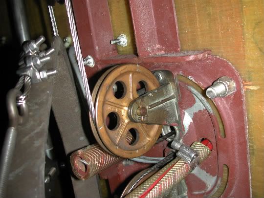
The problem
Russell, for comparison, here's a before shot (sorry, don't have an after). The pedestal guard bolts are the two smaller ones above the sheave, one of which penetrates the square tubing and is partially behind the cable. Easy to tell that a hole to feed wires up the guard tube would go through the sidewall of the tube and weaken it substantially...not good.
I thought about trying to drill through the sole at an angle but I didn't want to remove the weldment and didn't want to risk damaging it either. Moving the guard tubes seemed, as you say, the more elegant solution.
If I recall correctly, the top plate was also out of production but they had some in stock...you may want to call and see if it's still available. I imagine a machine shop could knock something up by copying your current top plate with a 2" extension...the critical dimension is the c-c distance of the bores for the guard tubes.
-
John Danicic

- Posts: 594
- Joined: Feb 5th, '05, 10:30
- Location: CD 36 - Mariah - #124 Lake Superior
- Contact:
Dedicated wire post
Russell:
On Mariah, all the instruments are on the pedestal. At first all the wires were bundled and ran inside the pedestal up along the shift and the throttle cables. This was not a good arrangement but worked until the steering chain cut the speed cable and I wanted to add a GPS and windlass switch to the mix. I decided to move all the wires to a separate tube that I made by gluing up two "L"s of teak to make a box tube, about 1.5 x 1.5 inch wide that runs along side the pedestal from the nav pods arms to the deck just outside of the metal plate area. A simple 1 inch hole drilled into the cockpit deck, well sealed and seated with a collar around the tube allows more wires then I should ever have or need run from hither to yon well away from the steering mechanics.
The teak tube was easy to make and I finished it with varnish. I was worried that it would be a foot grabber but after three seasons of use, I found that it is not a problem.
Sail on
John Danicic
CD 36 -Mariah- #124
Lake Superior
-
Steve Laume

- Posts: 4131
- Joined: Feb 13th, '05, 20:40
- Location: Raven1984 Cape Dory 30C Hull #309Noank, CT
- Contact:
I ran an extra wire conduit for my chart plotter/radar installation. I didn't want to get into changing the pedestal guard to a 1&1/4" size so I added a third leg. It is standard bimini fittings. A flange at the deck then a 1" tube with a rubber grommet in the top that ends just below the compass. It looks neat and tidy without changing a bunch of stuff to accommodate the larger pedestal guard. No extra brightwork either although the teak conduit must look very nice, Steve.
-
Parfait's Provider

- Posts: 764
- Joined: Feb 6th, '05, 13:06
- Location: CD/36 #84, Parfait, Raleigh, NC
berthed Whortonsville, NC
Snuck By
When I added the chart plotter I was able to sneak the cables past the steel and into the guard, but I don't think it is worth the trouble. I am now faced with moving the autopilot head and the depth/speed instrument to the helm and I am going to have to do something different. A third tube of stainless seems like a good idea. I sure don't need any more dull work.
Keep on sailing,
Ken Coit, ND7N
CD/36 #84
Parfait
Raleigh, NC
Ken Coit, ND7N
CD/36 #84
Parfait
Raleigh, NC
-
Cathy Monaghan

- Posts: 3502
- Joined: Feb 5th, '05, 08:17
- Location: 1986 CD32 Realization #3, Rahway, NJ, Raritan Bay -- CDSOA Member since 2000. Greenline 39 Electra
- Contact:
Hi Russell,
I have a CD32, but we have the same Edson steering system.
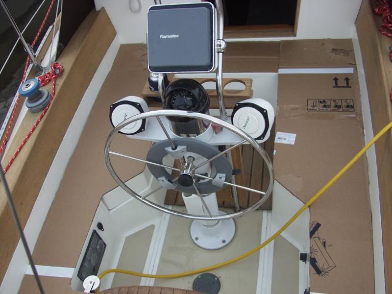
I have the displays for both the knotmeter/knotlog and the depthsounder mounted at the binnacle as well as a combo radar/chartplotter. I also have a wheel-mounted autopilot. You can see the instruments at the binnacle in this photo:
<A href="http://i30.photobucket.com/albums/c349/ ... orward.jpg" target="_blank"><img width="600" src="http://i30.photobucket.com/albums/c349/ ... d.jpg"></a>
(All that cardboard in the photo above is the template I was making for new cockpit cushions.)
All of the wiring for the depthsounder, knotmeter/knotlog and the autopilot run through the pedestal itself. And all of the wiring for the radar/chartplotter runs through the pedestal guard legs -- 3 on one side and 2 on the other.
We had to drill the holes beneath the guard feet on an angle in order to avoid drilling through the conduit bracket for the sheaves and rudder stop.
You can make out the wiring coming from the holes beneath the guard feet in the photo below. [I'm in the process of installing the autopilot, specifically the rudder reference sensor, in this photo. The wires are a mess in the photo because they all used to be routed through the middle of the quadrant and I had to re-route them in order to install the bracket (home made) for the rudder reference sensor to the quandrant.]
<a href="http://i30.photobucket.com/albums/c349/ ... G_0659.jpg" target="_blank"><img width="600" src="http://i30.photobucket.com/albums/c349/ ... 9.jpg"></a>
The wiring that runs through the pedestall itself exits behind the conduit bracket.
Cathy
CD32 Realization, #3
Rahway, NJ
Raritan Bay
I have a CD32, but we have the same Edson steering system.
I have the displays for both the knotmeter/knotlog and the depthsounder mounted at the binnacle as well as a combo radar/chartplotter. I also have a wheel-mounted autopilot. You can see the instruments at the binnacle in this photo:
<A href="http://i30.photobucket.com/albums/c349/ ... orward.jpg" target="_blank"><img width="600" src="http://i30.photobucket.com/albums/c349/ ... d.jpg"></a>
(All that cardboard in the photo above is the template I was making for new cockpit cushions.)
All of the wiring for the depthsounder, knotmeter/knotlog and the autopilot run through the pedestal itself. And all of the wiring for the radar/chartplotter runs through the pedestal guard legs -- 3 on one side and 2 on the other.
We had to drill the holes beneath the guard feet on an angle in order to avoid drilling through the conduit bracket for the sheaves and rudder stop.
You can make out the wiring coming from the holes beneath the guard feet in the photo below. [I'm in the process of installing the autopilot, specifically the rudder reference sensor, in this photo. The wires are a mess in the photo because they all used to be routed through the middle of the quadrant and I had to re-route them in order to install the bracket (home made) for the rudder reference sensor to the quandrant.]
<a href="http://i30.photobucket.com/albums/c349/ ... G_0659.jpg" target="_blank"><img width="600" src="http://i30.photobucket.com/albums/c349/ ... 9.jpg"></a>
The wiring that runs through the pedestall itself exits behind the conduit bracket.
Cathy
CD32 Realization, #3
Rahway, NJ
Raritan Bay
Last edited by Cathy Monaghan on Oct 13th, '10, 14:12, edited 2 times in total.
Re: Snuck By
Ken,Parfait's Provider wrote:When I added the chart plotter I was able to sneak the cables past the steel and into the guard, but I don't think it is worth the trouble. I am now faced with moving the autopilot head and the depth/speed instrument to the helm and I am going to have to do something different. A third tube of stainless seems like a good idea. I sure don't need any more dull work.
If all your insturments are moving to the same spot as the chatplotter, you may not really be faced wtih that much more wire, are they all networked via nema2000/seatalk/whatever? If so its possible that your existing wires going to the plotter are all you need.
Russell
s/v (yet to be named) Tayana 42CC
s/v Lady Pauline Cape Dory 36 #117 (for sale)
s/v (yet to be named) Tayana 42CC
s/v Lady Pauline Cape Dory 36 #117 (for sale)
-
Parfait's Provider
- Posts: 764
- Joined: Feb 6th, '05, 13:06
- Location: CD/36 #84, Parfait, Raleigh, NC
berthed Whortonsville, NC
OH, I Wish
Unfortunately, I am pulling some gear from a different century into the pedestal area. Until is it time to toss it all out, I will using Raymarine chartplotter/RADAR, a B&G quad, and an Alpha Marine autopilot which is rugged but very vintage. I doubt they will talk to one another.
I have found an engine pod that Catalina uses on the pedestal; I hope they are really still available: http://store.oceanequipment.com/Product ... ctid=EP162.
I have found an engine pod that Catalina uses on the pedestal; I hope they are really still available: http://store.oceanequipment.com/Product ... ctid=EP162.
Keep on sailing,
Ken Coit, ND7N
CD/36 #84
Parfait
Raleigh, NC
Ken Coit, ND7N
CD/36 #84
Parfait
Raleigh, NC