johnc,
That rebar structure looks like part of a fix that was "engineered" and installed after the problem appeared. I suspect it's a boatyard job, not something from Cape Dory.
I'm sure you're perfectly capable of figuring out what to do about this. However, I thought I would offer my thoughts about how I might proceed if I were in your place. I believe I would remove all traces of repairs made subsequent to original manufacture, and all traces of the original steel backing plate. I would plan to replace the steel with solid fiberglass. If I observed the problem first hand I would refine this plan, but the repair would probably go someting like this:
Remove all the dirt and previously applied sealants.
Make or otherwise acquire a piece of solid fiberglass of a size and shape similar to the steel that was removed.
Also get a second piece of ready-made fiberglass to install under the hull flange as secondary backing. This piece should be reasonably large, to distribute the backstay loads beyond the damaged area.
Fit all this together "dry" using "throw away" steel bolts from the hardware store.
Add shims (which will become permanent) as necessary to ensure that the bottom of the lowest piece of FRP is parallel to the deck upper surface.
Take it all apart and thoroughly wax the bolts.
Then mix up a batch of epoxy thickened with cabosil (or talc) and some milled fiber (or finely chopped fiberglass). Use SLOW cure hardener to give yourself plenty of time.
Put all the parts back together using enough spooge to fill all voids and bind everything together. Just "snug" the bolts, don't tighten them.
While the spooge is still uncured, fillet as necessary to make the repair attractive.
When it's all cured, remove the bolts using light taps of the hammer or whatever. At this point, if you're able to use the holes, you're nearly done. However, if you need to move the holes or improve the alignment, you can fill these holes. Use a slightly larger drill to open the holes and make sure you get rid of any wax. Put tape on the bottom and fill them with epoxy. Once it's cured you can drill new, perfectly sized and aligned holes.
The "spooge" should be made with enough cabosil to make it like mayonaise or peanut butter, so it will stay where you put it but still squeeze out easily when you pull everything together. It should also have enough glass fibers in it to improve strength.
All new pieces and the old areas to which they are bonded should be cleaned, then cleaned again with acetone, then sanded. Don't clean again after sanding; let the freshly sanded surface be the bonding surface.
One possible "fly in the ointment" with this plan: If the hull flange was torn away from the transom, the repair will need to be modified to address this. The piece I referred to as the "second piece of ready-made fiberglass to install under the hull flange as secondary backing" would need to be more complex. Rather than just a flat piece, it would need to be "L" shaped to fit to the bottom of the flange and to the inside upper transom. This piece, when bonded to both the flange and the transom, would "fix" the tear. I would still do it with a pre-made part, since this is such a difficult space to work in. You could make a simple mold from plywood, aluminum or whatever, wax it, build up the part in it, let it cure, remove it, trim it, sand it, fit it in dry, and then proceed as previously outlined.
I wish I was there so I could see it! I believe you can make this as good as or better than new.
GOOD LUCK!
Backstay lifting deck at hull joint
Moderator: Jim Walsh
-
Troy Scott
- Posts: 1470
- Joined: Jan 21st, '06, 01:23
- Location: Cape Dory 36 IMAGINE Laurel, Mississippi
backstay attachment repair
Regards,
Troy Scott
Troy Scott
Details
Troy,
What you describe fits nicely with what I have been contemplating.
Since this is not something I have any experience with my biggest issue is always in the details. You filled in several details that I either hadn't considered or hadn't quite worked out.
It seems that every time a new posting is made another detail falls in place. Keep the ideas coming.
This is starting to be fun! Of course that will change when I have to start grinding :^)
John
-
Troy Scott
- Posts: 1470
- Joined: Jan 21st, '06, 01:23
- Location: Cape Dory 36 IMAGINE Laurel, Mississippi
grinding
John,
I have a random orbital sander that connects to my vacuum cleaner. This helps a lot. When I grind and can't constantly vacuum, I use a HOBBY AIR breathing system to bring in clean air. I position the machine to pick up air straight out of the air conditioner. Don't breathe fiberglass dust!
Also, when working with acetone and epoxy, use disposable gloves. Constant contact with acetone will dry your skin, and constant contact with epoxy will cause you to develop a severe allergy. When working with epoxy, be especially careful if you need a bathroom break. Accidentally touching "down there" with a little epoxy on your hands can lead to irritation and itching.
If you do happen to get a lot of fiberglass dust on your skin, don't brush it off; that rubs it in. Take a COOL shower using a mild soap. Hot water opens the pores and makes the problem worse.
Regards,
Troy Scott
Troy Scott

Don't laugh it helps... Before lathering up take a pair of nylon, or whatever they are made of, stockings or pantyhose and wipe yourself down with them. The nylons snag the fiberglass particles and helps remove them. It also helps pull the fibers out of your pores. An old timer told me about it years ago and I swear by it now. Like Troy said don't breath the stuff. I have been told by several people that fiberglass particles are NEVER expelled by your lungs and has a cumulative effect. Cannot be good! Something to keep in mind when choosing a paper mask or a respirator.
Lee
S/V Solomon Lee
S/V Solomon Lee
-
S/V Necessity
- Posts: 147
- Joined: Jun 13th, '06, 23:38
- Location: 1981 CD28 #305
Columbia, MO
Cool Shower
Troy is right, the cool shower helps considerably (I use COLD water though). It's really tough to step into a shower that isn't hot, but It's worth it later on.... Scrubbing with a brush towards the end helps some to. Best yet, cover up well and throw the clothes away afterwards. Also it's probably wise to avoid breathing any inorganic fibers, be careful.
-
Ocean Girl
- Posts: 82
- Joined: Aug 30th, '08, 21:07
- Location: 1981 Cape Dory 30 cutter, located at Waterford Harbor, Clear lake, Texas
- Contact:
lint roller
Tape (blot it)or a Tape style lint roller helps to get fiberglass off.
and always roll in one direction so you don't rub it in. I would also powder up with baby powder before grinding and that seemed to help keep some of the glass off me.
Have fun!
Erika
and always roll in one direction so you don't rub it in. I would also powder up with baby powder before grinding and that seemed to help keep some of the glass off me.
Have fun!
Erika
There is nothing like lying flat on your back on the deck, alone except for the helmsman aft at the wheel, silence except for the lapping of the sea against the side of the ship. At that time you can be equal to Ulysses and brother to him.
- Errol Flynn
PS I have a blog now!
http://oceangirlcd30.blogspot.com/
- Errol Flynn
PS I have a blog now!
http://oceangirlcd30.blogspot.com/
Switching from deck pad eye to an external chain plate
John,
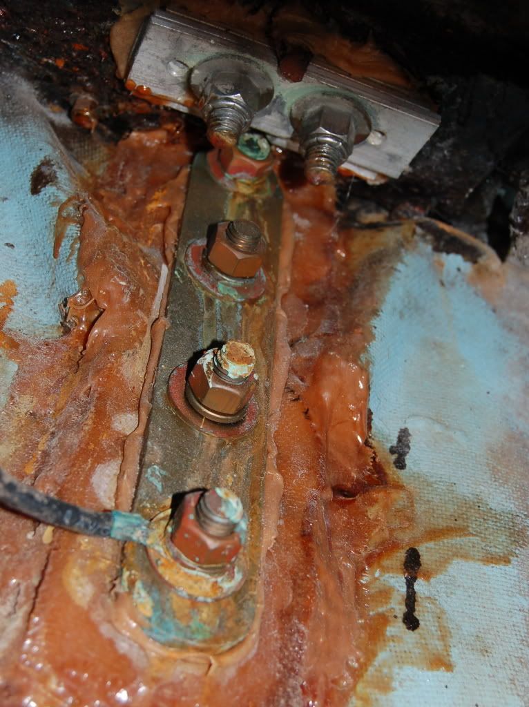
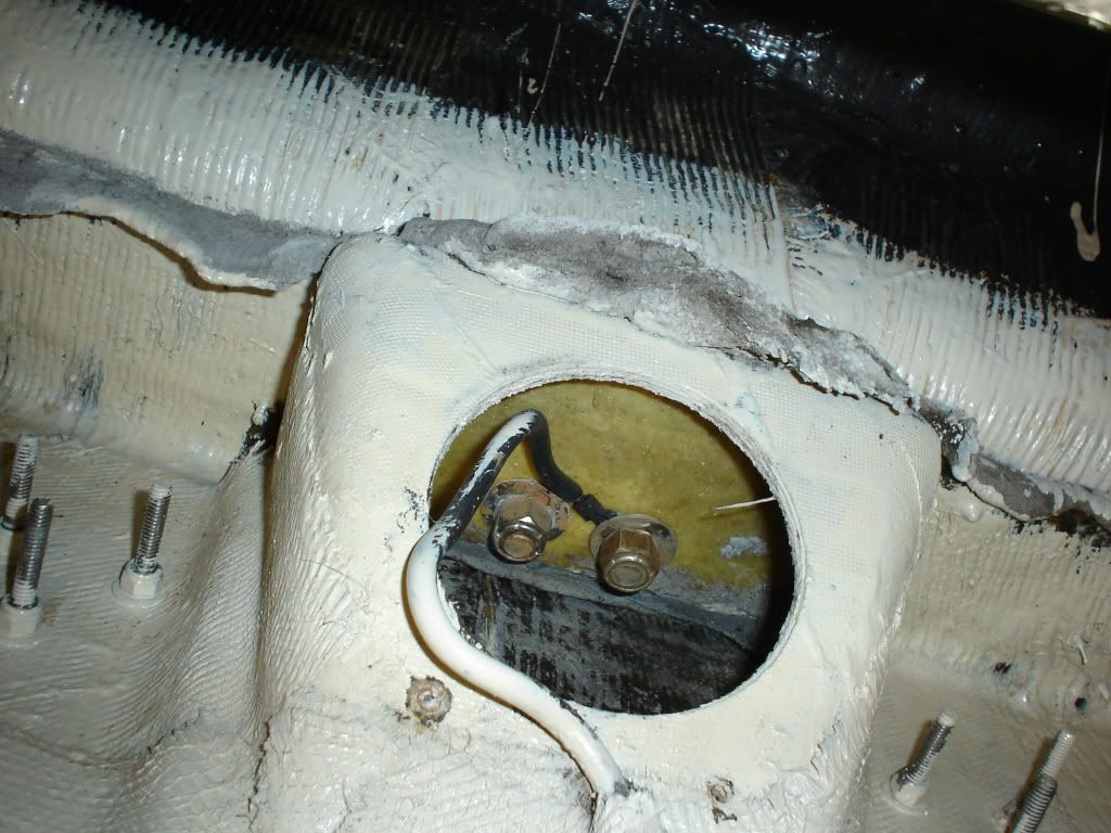
I had a similar problem that developed on Zephyr about three years ago. I noticed a slight lifting of the aft edge of the deck and a tilting forward of the deck pad eye that was used to secure the back stay. When I checked the under side, the backing plate and the supporting rebar---yes rebar!---were heavily rusted.
I made several attempts to repair and reinforce this set up by using phosphoric acid rust treatment, thickened epoxy, additional backing plates (aluminum) and additional bolts and nuts. But the material had deteriorated too much and I went to plan B, which was to switch to an external chain plate.
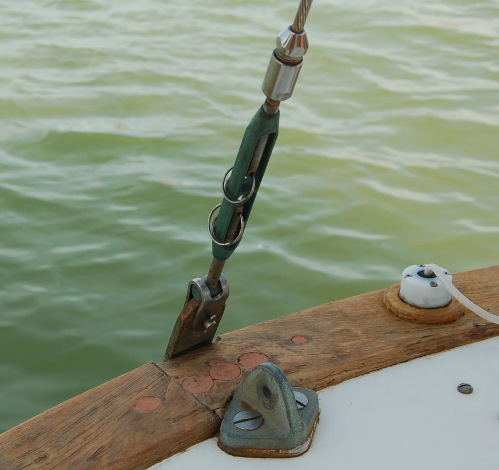
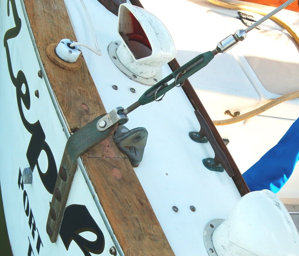
I used 1/4 inch bronze flat stock for the chain plate, identical bronze for a backing plate, and bronze fasteners---carriage bolts, flat washers, lock washers and nuts. I had a local machine shop bend the chain plate for me. (BTW, 1/4 inch bronze plate is actually closer to 5/16 inch. The machinist said this is SOP because most bronze is used for bearings and has to be machined down so they make it thicker to allow for loss during machining.)
To make the carriage bolts work, I rounded off two of the square shoulders and then squared two sides of the holes in the chain plate. This produced a round load bearing mating surface with square nonload bearing surfaces to prevent the bolts from turning while being tightened. I built up the transom under the backing plate using thickened epoxy.
This was a relatively simple job made way more complex because of limited access to the backing plate area. I literally could only use one hand while lying on the cockpit seat with my head dangling over behind the rudder post area. (What is the sound of one hand epoxying? I don't know. I couldn't hear it over my grunts, groans, curses, and gnashing of teeth.) Here are some pics:
[img][img]http://i199.photobucket.com/albums/aa12 ... C_0038.jpg[/img]
If the job looks a little sloppy, it is. See above note about one hand only. At the top can be seen the futile efforts to repair the original backing plates. I put the bronze backing plate in place before the last layer of epoxy had set to get a flat, fair surface.
[/img][img]http://i199.photobucket.com/albums/aa12 ... C_0041.jpg[/img]
I cut the chain plate to a length that would allow attaching the back stay without changing its length. Scars in the teak cap rail are from the unsuccessful attempt to repair the original set up. (I'm in the process of refinishing the teak here.)
[img][img]http://i199.photobucket.com/albums/aa12 ... C_0042.jpg[/img]
This is the finished project. I tried to make it so that 500 years from now, it will be the last surviving remnant of my boat.
Hope this helps. Bob
I had a similar problem that developed on Zephyr about three years ago. I noticed a slight lifting of the aft edge of the deck and a tilting forward of the deck pad eye that was used to secure the back stay. When I checked the under side, the backing plate and the supporting rebar---yes rebar!---were heavily rusted.
I made several attempts to repair and reinforce this set up by using phosphoric acid rust treatment, thickened epoxy, additional backing plates (aluminum) and additional bolts and nuts. But the material had deteriorated too much and I went to plan B, which was to switch to an external chain plate.
I used 1/4 inch bronze flat stock for the chain plate, identical bronze for a backing plate, and bronze fasteners---carriage bolts, flat washers, lock washers and nuts. I had a local machine shop bend the chain plate for me. (BTW, 1/4 inch bronze plate is actually closer to 5/16 inch. The machinist said this is SOP because most bronze is used for bearings and has to be machined down so they make it thicker to allow for loss during machining.)
To make the carriage bolts work, I rounded off two of the square shoulders and then squared two sides of the holes in the chain plate. This produced a round load bearing mating surface with square nonload bearing surfaces to prevent the bolts from turning while being tightened. I built up the transom under the backing plate using thickened epoxy.
This was a relatively simple job made way more complex because of limited access to the backing plate area. I literally could only use one hand while lying on the cockpit seat with my head dangling over behind the rudder post area. (What is the sound of one hand epoxying? I don't know. I couldn't hear it over my grunts, groans, curses, and gnashing of teeth.) Here are some pics:
[img][img]http://i199.photobucket.com/albums/aa12 ... C_0038.jpg[/img]
If the job looks a little sloppy, it is. See above note about one hand only. At the top can be seen the futile efforts to repair the original backing plates. I put the bronze backing plate in place before the last layer of epoxy had set to get a flat, fair surface.
[/img][img]http://i199.photobucket.com/albums/aa12 ... C_0041.jpg[/img]
I cut the chain plate to a length that would allow attaching the back stay without changing its length. Scars in the teak cap rail are from the unsuccessful attempt to repair the original set up. (I'm in the process of refinishing the teak here.)
[img][img]http://i199.photobucket.com/albums/aa12 ... C_0042.jpg[/img]
This is the finished project. I tried to make it so that 500 years from now, it will be the last surviving remnant of my boat.
Hope this helps. Bob
-
Troy Scott
- Posts: 1470
- Joined: Jan 21st, '06, 01:23
- Location: Cape Dory 36 IMAGINE Laurel, Mississippi
-
fenixrises

- Posts: 450
- Joined: Feb 13th, '05, 08:01
- Location: SunShine S2 11c
- Contact:
A side note
Hi all,
If you use SS for chain plates do not have square holes cut or punched in the flat bar for carriage bolts. The "corners" of the squares make stress risers in the SS. Far better to drill round holes and use hex bolts. Even short hex bolts also usually have a smooth shank for some distance before the threading starts. That means the shear load is across a solid bar not notched by threads.
Plus hex bolts are easier to tighten and loosen.
This is not true for most carriage bolts.
Take care,
Fred
You should always have an odd number of holes in your boat!
Pictures from MkII
Hi John:
Here are the details of how CD made the connections on the MkII I had mentioned.
[/img]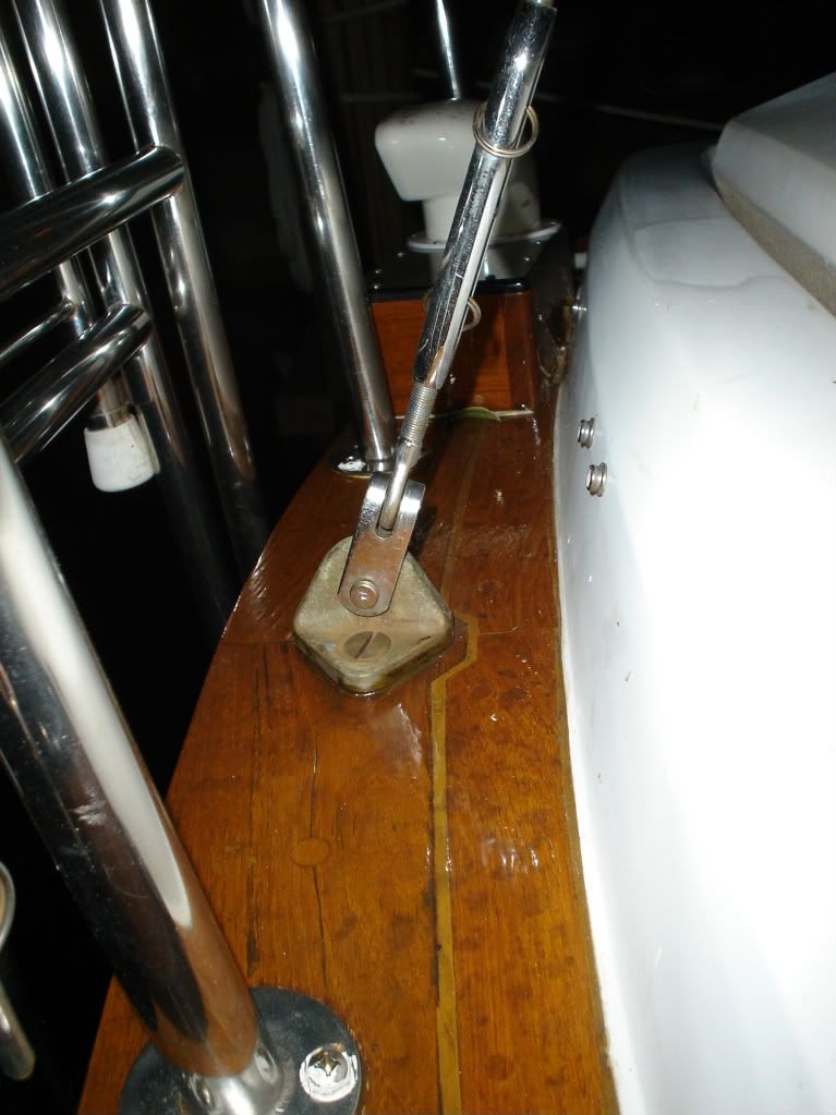
This is the backstay to deck connection. Note there is a lot of geometric strength in the deck at this point due to the cockpit curb.

This is the underside of the backstay joint. The "oozing" substance at the hull/deck joint is a polyester putty that CD used to make the joint. It looks like they added a thick backing plate that was glassed to the stern before they tabbed the premade "bracket" to the hull. I suspect the access hole was drilled before they put this in place as it seems impossible to do after.
[/img]
This is just another shot of the same place.

This is the "box" I was refering to in my earlier post. Again, this appears to be premade and tabbed in place later. This box extends forward and holds all three side stays. It is about 4' long
[/img]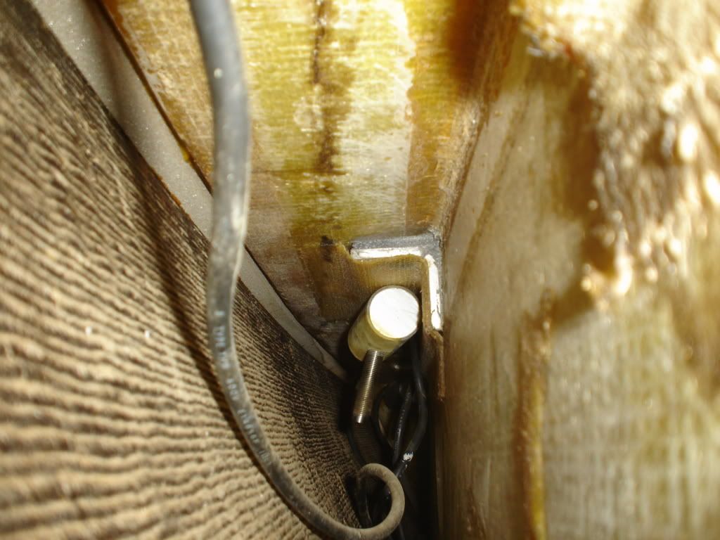
This is inside the "box". The aluminum angle is set in the same putty as the hull/deck joint. The SS rod is threaded into the 1"+ bronze rod.

This is the connection under the deck to the SS rod.
Hope this helps in your search for a solution.
Boyd
s/v Tern
CD30 MkII
Fort Lauderdale, Fla. [/img]
Here are the details of how CD made the connections on the MkII I had mentioned.
[/img]
This is the backstay to deck connection. Note there is a lot of geometric strength in the deck at this point due to the cockpit curb.
This is the underside of the backstay joint. The "oozing" substance at the hull/deck joint is a polyester putty that CD used to make the joint. It looks like they added a thick backing plate that was glassed to the stern before they tabbed the premade "bracket" to the hull. I suspect the access hole was drilled before they put this in place as it seems impossible to do after.
[/img]
This is just another shot of the same place.
This is the "box" I was refering to in my earlier post. Again, this appears to be premade and tabbed in place later. This box extends forward and holds all three side stays. It is about 4' long
[/img]
This is inside the "box". The aluminum angle is set in the same putty as the hull/deck joint. The SS rod is threaded into the 1"+ bronze rod.
This is the connection under the deck to the SS rod.
Hope this helps in your search for a solution.
Boyd
s/v Tern
CD30 MkII
Fort Lauderdale, Fla. [/img]
Padeye position
Boyd,
While studying your pictures something appeared different when looking at the underside of your deck. Initially I couldn't put my finger on it but, eventually, I realized that the holes for the padeye bolts on your backstay appeared closer to the transom than mine. On your boat the bolts go through the hull flange, on my boat the bolts are not anywhere near the flange. It's more noticeable from the underside but I'm thinking that even an inch or so might make a difference when you consider the forces on the backstay but even more important when you consider that whatever holds the backstay down is going to be pulling down on an angle back to the transom. The closer the angle is to vertical the more strength the tiedown will have.
As an example consider Zephyr's chainplate. It is flush to the bonding surface with no additional trusses transferring any of the load. It's load vector is perfectly vertical to the transom.
The reason the "Thing" has three legs and not two, like the shrouds, is that the forces are not close enough to the vertical.
[img]http://www.geocities.com/johnfconnolly2 ... EkHLPM.jpg[/img][img]http://www.geocities.com/johnfconnolly2 ... 5ThaPM.jpg[/img][img]http://www.geocities.com/johnfconnolly2 ... 7CqMPM.jpg[/img]
On the left MkII, in the middle CD28 (Zephyr), right FêNIX's "Thing"
-
Troy Scott
- Posts: 1470
- Joined: Jan 21st, '06, 01:23
- Location: Cape Dory 36 IMAGINE Laurel, Mississippi
backstay chainplate structure
In my 1988 CD36 (#152) the backstay chainplate reinforcement is made like Boyd's second and third photos. The only change I will make in my refit will be to add a 1/2" thick fiberglass backing plate inside the "box". I will make it as large as I can, and make sure it's parallel to the deck.
Regards,
Troy Scott
Troy Scott
-
Troy Scott
- Posts: 1470
- Joined: Jan 21st, '06, 01:23
- Location: Cape Dory 36 IMAGINE Laurel, Mississippi
backstay chainplate location
John,
I'm amazed your chainplate wasn't through-bolted through the hull flange. I think it was probably supposed to have been.
I'm amazed your chainplate wasn't through-bolted through the hull flange. I think it was probably supposed to have been.
Regards,
Troy Scott
Troy Scott
Padeye position
Troy,
If you look at the picture of the backing plate tri-pod structure, notice the distance between the bolt holes and the edge of the plate. The flange on my boat is about half the size of the backing plate. The backing plate will 'catch' the flange but the bolt holes are well beyond the flange.
The backing plates for my shrouds, what's left of them, do bolt through the flange but the padeyes for the shrouds are much closer to the hull than is the backstay padeye.
John